Tube Fest Talk, Part I
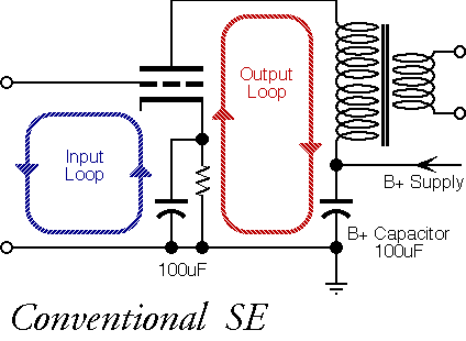
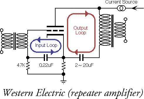
The signal path is actually a loop connecting sender and receiver. A vacuum-tube has a differential input (grid and cathode) and a differential output (plate and cathode). Differing impedances for the respective nodes, but the tube neither knows nor cares about chassis ground, nor input grounds.
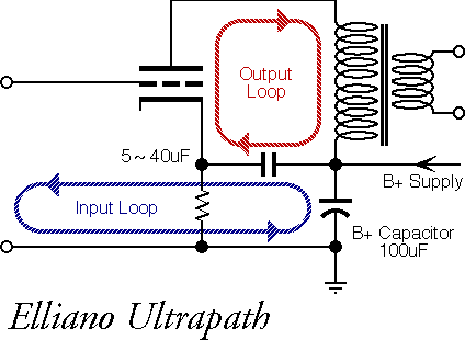
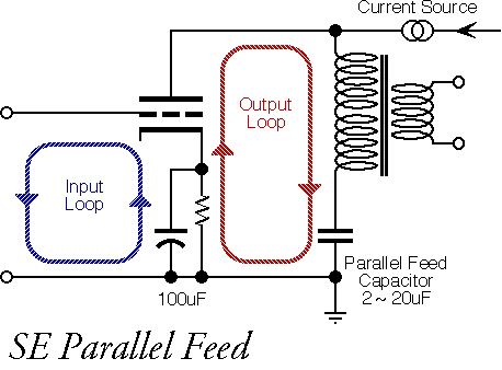
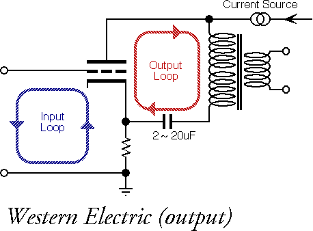
These days passive components are not automatically assumed to be sonically invisible, so you have count up the parts in this loop to understand where coloration may be coming from. In a conventional SE amplifier, for example, the output loop goes from plate -> OPT -> PS cap -> cathode-bypass cap -> return to cathode.
In many circuits the PS cap and cathode-bypass cap are electrolytics of opposite polarity, differing values, and different voltage-breakdown rating. What chance is there that cap-coloration will somehow magically disappear from this series-string of caps?
The same analysis applies to the input side - even though currents are very low, the differential input of the vacuum-tube is still affected by all the parts in series between the tube and source components. The tube doesn't amplify the grid signal - it amplifies the voltage difference between the grid and the cathode, so the cathode-side circuit matters just as much as the grid circuit.
The output loop between the plate and cathode carry large audio-frequency currents, while the input loop between the grid and the cathode carry very small (but not zero) audio-frequency currents. Both loops are sensitive to the parts that are used in the loop - the triode, transformer, capacitors, and who knows, the wire itself.
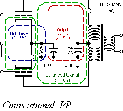
All PP or differential amplifiers are really two amplifiers operating in parallel: a perfectly balanced PP amp, and a secondary SE amplifier running 26-30dB down from the main PP amplifier. This secondary, "shadow," amplifier is the sum of all imbalance terms in the tubes and transformer primary, typically 2~5%. You can try various nulling schemes, but this makes the problem worse, not better, because as the residual approaches zero, you start to see frequency and phase-dependent terms appear. In other words, the null will only be at one frequency and power level, and will skip around on both sides of the null under real-world conditions.
Deliberately increasing imbalance, such as 20-30%, using dissimilar tubes or unequal grid feeds, seems to have the worst of both SE and PP worlds, maximizing the coloration of each type. The best approach, sonically and electrically, is the simplest: let the tubes find their own degree of imbalance, and design the circuit around that.
Functionally, assume the top tube is running at 105% gain, while the lower tube is running at 100% gain. The net overall gain is 102%, and the gain of the imbalance signal is 5%. The imbalance signal has almost no effect on overall gain or frequency response, but is responsible for all of the even-order distortion and power-supply noise getting into the circuit. The imbalance audio-frequency currents flow through the cathode circuit in the same way as a SE amplifier, favoring whichever tube has the most gain at the moment.
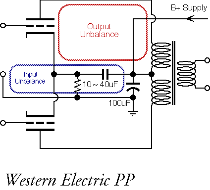
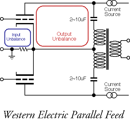
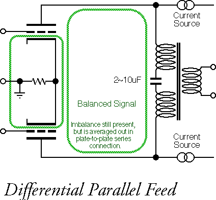
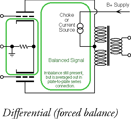
When the circuit is forced into differential mode with a choke or current source, that means when one tube is removed, the circuit stops amplifying. The two tubes are effectively in series, just like a Christmas-tree string of lights. This creates a "composite tube" with the vector-sum averaged characteristics of both tubes. These circuits remain in Class A at all times; if one tube runs out of gain (stops working), the circuit simply clips.
The other PP circuits allow the tubes to operate independently; if one tube is removed, the circuit keeps on amplifying. The tubes are then effectively in parallel, not series, and I suspect the composite transfer curves look a bit different.
These circuits are "Class AB-capable"; although normally biased into Class A, if the load demands more current than the quiescent bias point, the "on" tube will deliver several times the quiescent current, and the "off" tube will go to zero current. The choice of where to place the AB transition point is up to the designer - in Class A circuits, this is placed well above normal operating conditions. If the designer chooses to double the wattage of a power amplifier for a given circuit, the Class AB transition can be as low as 1 watt or less (not unusual in transistor amplifiers, by the way).
Text © Lynn Olson 2003. All Rights Reserved.